3D Items
A geometry is the virtual 3D anolog of any component in the fire model . For example a switch gear could be represented by its geometry. The geometry is either modeled in an alternate CAD package such as Solidworks and can be imported in FRI3D.
Or a proxy representation of that geometry or component can be created in FRI3D at the appropriate location by first creating that component in the compartment inspector and with drag/drop into the 3D area as indicated by the following figure.
After placing the initial proxy geometry in FRI3D, there are several CAD modeling tools that exist which can be used to further mould that component or geometry.
Boundaries#
A compartment can be considered as a union of its boundaries. Each compartment can consist of one or multiple boundaries in which components are enclosed.
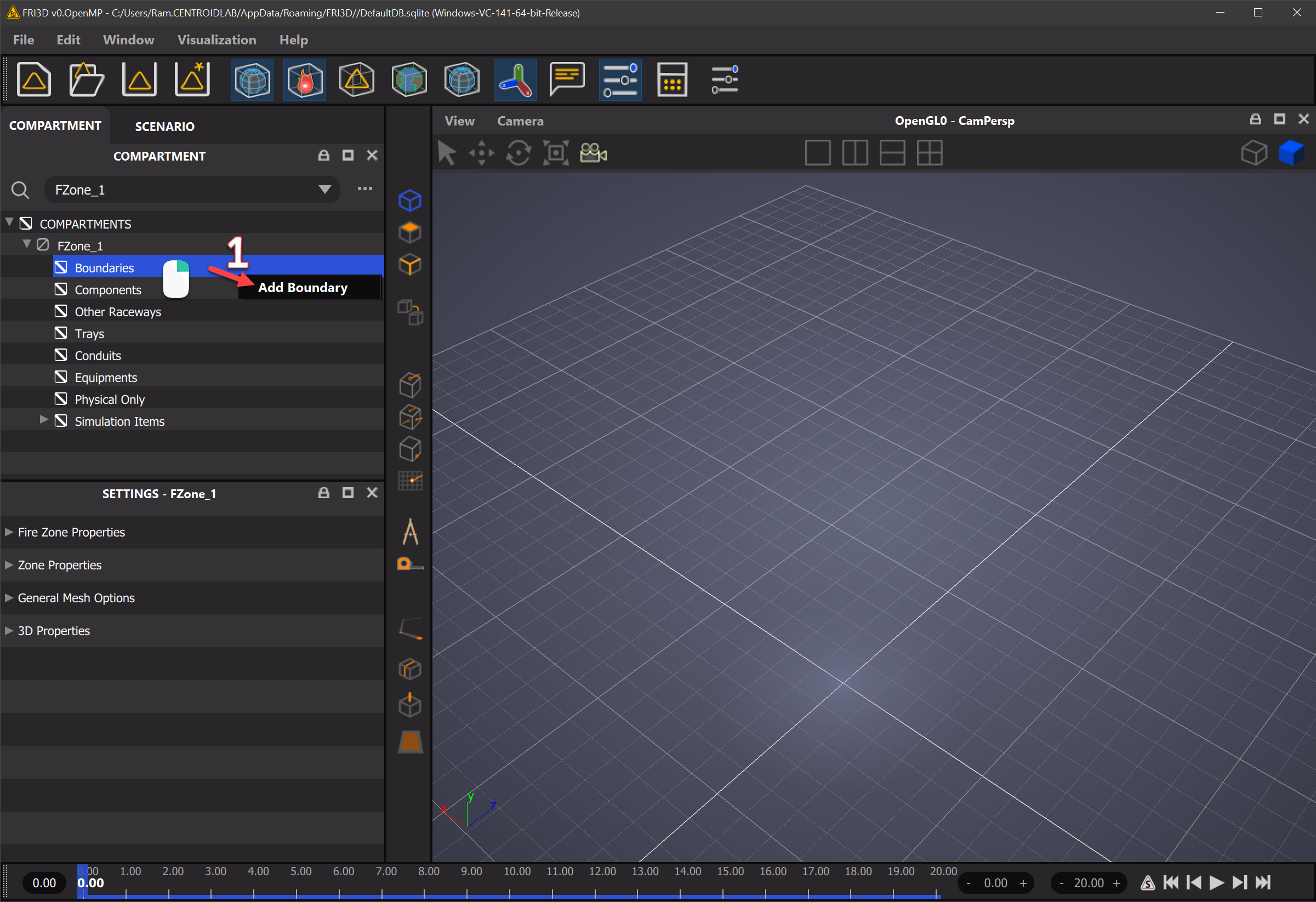
A default boundary cuboid is created when a new boundary is created in the interface as indicated below.
Boundary
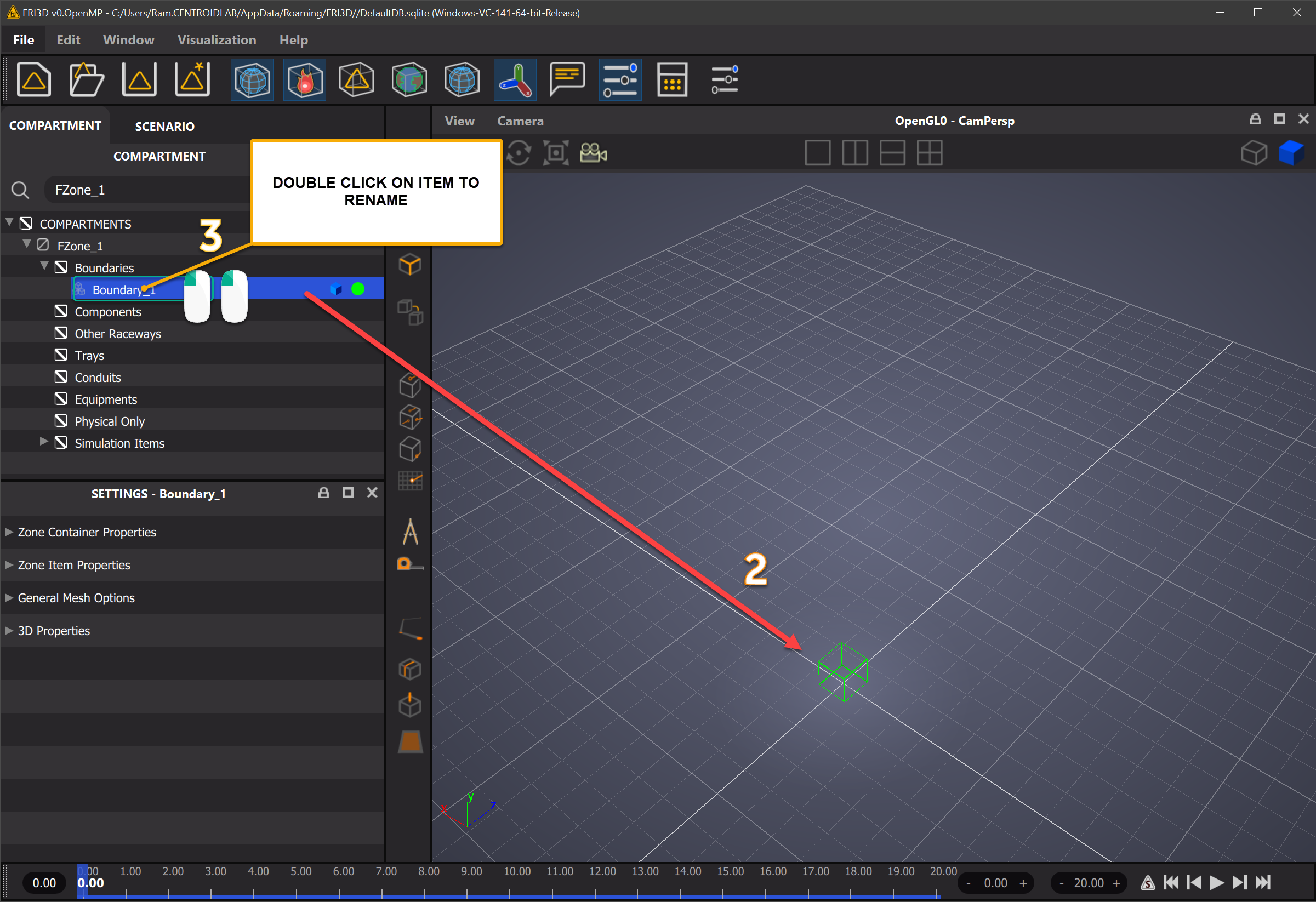
The boundary created can be renamed as follows
Boundary Rename
Additional boundaries can be created with their walls touching each other to make a more complex looking boundary. or these cuboidal default boundary shapes can be later modified by basic, intermediate or advanced CAD operations as described in further sections.
More details on enforcing constraints on movement , scaling etc which can enable further CAD modeling to enable users to create adjacent boundaries touching each other or creating boundaries with the same height etc are explained in CAD modeling section.
The union of all the boundary objects comprises of the compartment itself.
Components#
Components are items which are part of the compartment and scenario to be modelened. Components are created in the Compartmnent Inspector view and their 3D geometry associated.