3D Modeling in FRI3D
3D Modeling in FRI3D#
3D Modeling Overview#
3D Modeling systems help their users by performing thousands of complex geometrical calculations in the background without anyone having to even think about it to represent an object in a 3 dimensional background from a viewpoint of a camera which can be manipulated.
3D Modeling software make the engineers job a whole lot easier by which the engineer can create 3D proxy models representing real life geometry.
For example
- Creating a box representation of a complex geometry
3D models are used to portray real-world and conceptual visuals for art, entertainment, simulation and drafting and are integral to many different industries, including virtual reality, video games, 3D printing, marketing, TV and motion pictures, scientific and medical imaging and computer-aided design and manufacturing CAD/CAM.
FRI3D is not a full CAD modeling software but presents the user with manipulatable simplfied representations and focusing on creating Simulation friendly CAD models.
FRI3D allows the user to quickly create simplified 3D models by operations and performing the calculations on geometry to make sure that these models are well suited to perform simulation activities.
Example of highly complex shapes that are possible with FRI3D as a CAD Modeling tool.
Basic Modeling Operations#
The top tool bar in the modeling window has a set of tools which enable basic operations to manipulate the geometry. The geometry in this case is either a boundary (enclosure) or individual components enclosed by the boundary.
FRI3D organizes the 3D modeling toolkit into 2 different sections.
- Top Tool bar (To perform basic operations)
- Side Tool bar (To perform intermediate and advanced operations)
The Top bar#
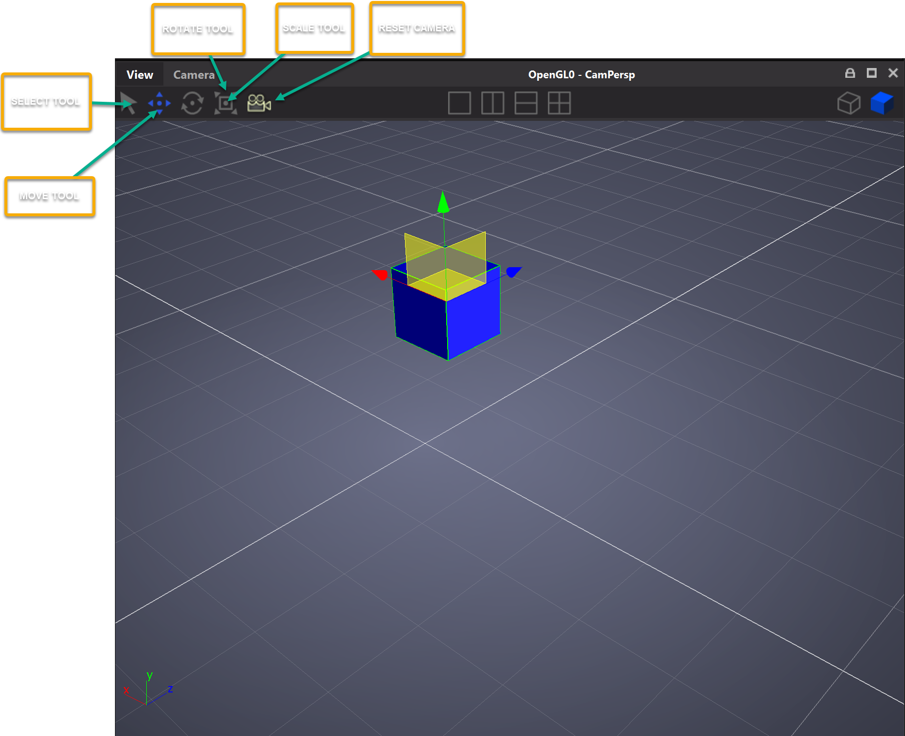
Select#
| Interaction | Keyboard/mouse | Touchpad/touchscreen |
|---|---|---|
| Select an object | Selection Mode (q) + Mouse selection | n/a |
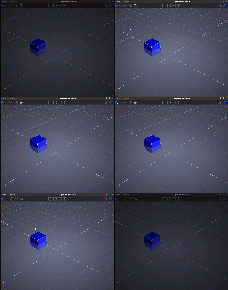
Move#
| Interaction | Keyboard/mouse | Touchpad/touchscreen |
|---|---|---|
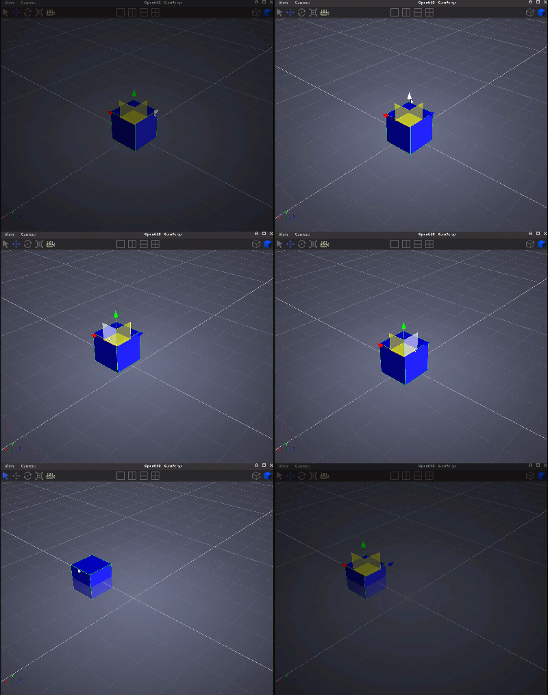
| Move an object | w + mouse handle move | n/a |
The following figure indicates a move operatio
Rotate#
| Interaction | Keyboard/mouse | Touchpad/touchscreen |
|---|---|---|
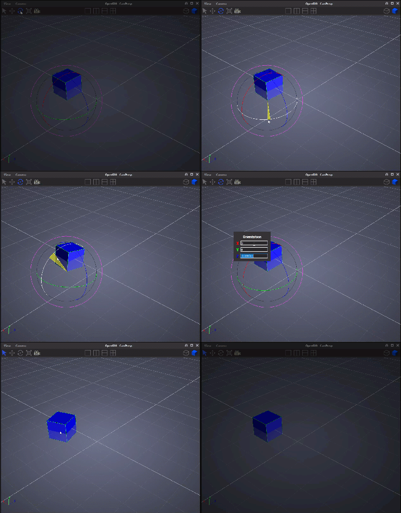
| Rotate an object | e + mouse rotate handles | n/a |
The following figure depicts a rotate operation
Scale#
| Interaction | Keyboard/mouse | Touchpad/touchscreen |
|---|---|---|
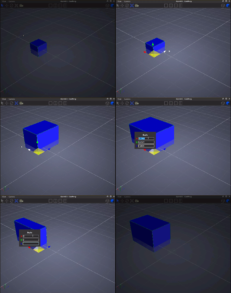
| Scale an object | r + mouse scale handles | n/a |
The following figure indicates a scale operation
Intermediate 3D Modeling Features#
Several features are present in user interface of FRI3D to facilitate and speed up model generation.
Snap#
It is possible force the item to be snapped onto another item in the direction of translation. The item and its face being snapped is automatically computed, based on which position the item is released. A regular plant item can be snapped onto either a boundary, another plant item, or the world grid; a vent can only be snapped onto a boundary.
Snap Movement#
The snap can be done with respect to another item in which when moved the object being manipulated is snapped to the boundaries of the nearest object in the direction of movement.
Snap resizing.#
If the user interactively resizes an item that is snapped onto another, the resizing can now be constrained with respect to the face of the other item it is snapped onto. If the direction of resizing was coplanar with the snapped face, then the effective resizing is limited to the extent of the dimensions of the snapping to face of the other item. If the direction of resizing was orthogonal to the snapped face, then the resizing is effectively applied only at the opposite side of the item. This feature is ideal for aligning cabinets and similar items that have a common length in one or more directions. (Currently, this feature is not correctly supported if the item being resized has several faces simultaneously in a snapped state but is being fixed.)
Incremental translation and resizing.#
The ability to force the interactive translation or resizing of an item is present through a click-drag-release and done incrementally based on a user-specified increment size. This enables the user to reposition items easily if their correct locations are known with a given rounding place. For example, if the locations are known up to the closest centimeter, then a relevant choice would be to set the increment size to 1 cm.
Point Distance Tool#
This tool enables the user to measure distances between exact points. For example two points on a floor plan.
Edge Distance Tool#
An interactive tool to measure distance between edges. This works by putting a marker on the edge of an item and another on the edge of another item, and the orthogonal distance between the two markers is calculated and displayed. The measured distance is dynamically recalculated, whenever one of the associated items is moved.