FLASH-CAT Methodology
FLASH-CAT Model
Overview
FRI3D uses the Flame Spread over Horizontal Cable Trays (FLASH-CAT) method, where applicable, to determine secondary combustion and fire propagation through cables. FLASH-CAT is an empirical method derived from controlled fire experiments conducted by the National Institute of Standards and Technology (NIST).
Applicability Conditions
For this empirical method to provide results approximating the NIST experiments, the following conditions must be met:
- The cable trays are horizontal and stacked vertically with a spacing of less than 0.45 m (18 in.)
- The cables burn in the open (i.e., they are away from walls and well below the ceiling)
- The cables are not exposed to elevated temperature sources except for the ignition source below
- There are no barriers separating the trays, and the tray tops and bottoms are open
- The cables are not protected with coatings, armor shielding, or thermal blankets of any kind
- There is a fire beneath the lowest tray
- Each tray has at least a single row of cables, or roughly 25% of the NRC limit
The FRI3D modeler is expected to model secondary combustibles following these limitations. The results of the secondary combustion simulation will not be accurate if, for example, there are several fire sources beneath a tray, nor will they be realistic if the raceways are relatively close to walls or ceilings.
Fire Propagation and Heat Release
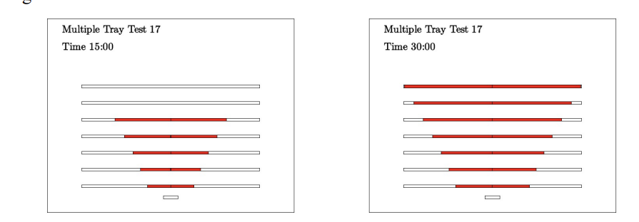
Fire spreads through a stack of trays in the characteristic V-shaped burning pattern observed in the NIST experiments: the fire ignites the tray directly above the source first, and each tray above it ignites over a progressively wider span as the fire propagates upward and outward along the trays.
The FLASH-CAT method divides a cable into several spatial segments. A cable segment combusts when the fire propagates to that segment. When it does, the heat release rate per unit area (HRRPUA) for that segment follows the time profile shown in the figure below, reflecting the dynamics of fire growth and decay. The HRR starts to increase at until reaching the peak HRRPUA one-sixth of later, remains stable until , and then decreases linearly to zero.
FLASH-CAT Time History
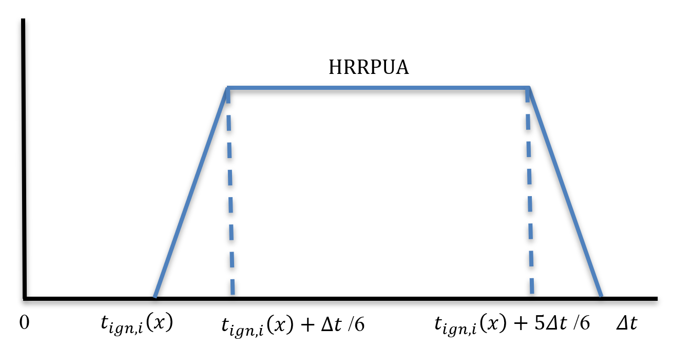
Time history of the local HRRPUA for each raceway grid.
Once the HRRPUA profiles for each raceway grid have been calculated, the HRR of the burning trays is calculated by summing the local HRRPUA profiles over all the trays:
Where is the HRR of the burning trays, is the width of tray , is the local HRRPUA, is the time the cable at point of tray ignites (below), and t is the discrete observation time. Each tray uses its own width. The HRRPUA and the combustible mass of every tray in a connected run are those of its most heavily loaded tray, the conservative choice.
When the Cables Ignite
Tray to tray, up the stack
- The lowest tray over the fire ignites when the source fire's flames reach its underside. If they never do, it ignites when its exposure passes the cable ignition threshold: 205 °C or 6 kW/m² for thermoplastic cables, 330 °C or 11 kW/m² for thermoset.
- Each tray above ignites 4, 3, 2, then 1 minute after the one below, the timing sequence of FLASH-CAT (NUREG/CR-7010).
- The initial burning length. On the lowest tray, a length equal to the width of the source fire ignites at once, centred over the fire, as NUREG/CR-7010 specifies. FRI3D takes the source's size in the direction the tray runs; a source with no size uses the diameter of its fire at its largest area. CFAST and FDS use the same length. Each tray above starts with a longer length, , where is the spacing between the trays. This produces the V-shaped pattern.
Along the trays
From the ends of the initial burning length, the fire spreads along the cables at a constant rate of 3.2 m/h for thermoplastic cables and 1.1 m/h for thermoset, in both directions. The cable at a distance from the fire, measured along the trays, ignites at:
Into connected trays
FRI3D links raceways that touch at the same level, and the fire carries on through those links:
- The fire passes from one tray into the next where they join. Where two trays overlap, it passes at the end of the overlap nearest the fire, so the two burn side by side as the front goes by.
- In the next tray it spreads both ways from the junction.
- Each point of every tray ignites when the front first reaches it, by the shortest route along the trays. Where a run branches or loops, the nearer route wins.
A tray directly over the fire therefore burns within seconds of the flames reaching it, while a tray joined to it 2.5 m along the run starts burning only when the front arrives, about 40 minutes later for thermoplastic cables.
FLASH-CAT itself describes one stack of straight trays, with the fire spreading "until the end of the tray is reached" (NUREG/CR-7010). Carrying the fire on into connected trays is FRI3D's extension of the method, consistent with the report's observation that FLASH-CAT tends to over-predict lateral spread rather than under-predict it.
A tray that ignites fails at its ignition time, with every cable it carries. See Raceway/Tray Failures.
How the Burning Trays Enter the Simulation
- CFAST: after the first CFAST run (the source fire alone), FRI3D works out the trays' HRR and ignition times, then reruns CFAST with the burning trays added as their own fire: one fire per tray stack, placed at the source's position and starting when the lowest tray ignites. Its HRR and burning area come from the sum above. This loop continues, since each rerun can ignite further raceways, until no additional secondary combustibles are found. CFAST releases the trays' heat as a single plume above the source, so flames spreading along a tray away from the source raise the hot gas layer but do not heat the targets next to that tray directly.
- FDS: the burning trays are written into the FDS input as burners on the trays themselves, each igniting on the FLASH-CAT timing, so the fire moves along the trays during the simulation.
Using FLASH-CAT in FRI3D
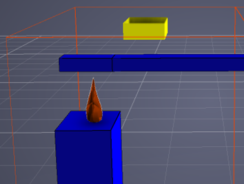
To use the FLASH-CAT methodology, position a raceway at a reasonably close distance above a fire source as shown in the screenshot below, and add cables inside the raceway to serve as the secondary combustible.
Note that the horizontal fire propagation rate in the FLASH-CAT methodology is relatively slow (in the range of 1–3 meters per hour). Cable raceways are typically long, so estimating the complete HRR profile of a secondary fire over the whole raceway length can require a simulation time of several hours; consider limiting the analyzed raceway length accordingly.
What's next?
- CFAST Simulations and FDS Output — the fire simulations that consume the combined HRR and produce the temperatures driving cable and equipment failures.
- Heat Soak and THIEF — the cable-failure calculations applied to the simulated exposure.