FRI3D での 3D モデリング
FRI3D での 3D モデリング
3D モデリングの概要
3D モデリングシステムは、操作可能なカメラの視点から 3 次元空間内にオブジェクトを表現するために必要な何千もの複雑な幾何計算を、ユーザーが意識することなくバックグラウンドで実行します。
3D モデリングソフトウェアを使うことで、エンジニア��は実在のジオメトリを表す 3D プロキシモデルを作成でき、作業が大幅に容易になります。
例:
- 複雑なジオメトリをボックス(直方体)で表現する
3D モデルは、アート、エンターテインメント、シミュレーション、製図などにおいて実世界や概念のビジュアルを表現するために使用され、バーチャルリアリティ、ビデオゲーム、3D プリンティング、マーケティング、テレビ・映画、科学・医用イメージング、そして CAD/CAM(コンピュータ支援設計・製造)など、数多くの産業に不可欠なものとなっています。
FRI3D はフル機能の CAD モデリングソフトウェアではありませんが、操作可能な簡略化された表現をユーザーに提供し、シミュレーションに適した CAD モデルの作成に焦点を当てています。
FRI3D では、各種操作によって簡略化された 3D モデルをすばやく作成でき、ジオメトリに対する計算を実行して、これらのモデルがシミュレーション作業に適した状態であることを保証します。
以下は、CAD モデリングツールとしての FRI3D で作成可能な、非常に複雑な形状の例です。
基本モデリング操作
モデリングウィンドウの上部ツールバーには、ジオメトリを操作するための基本操作を行う一連のツールが用意されています。ここでのジオメトリとは、バウンダリ(エンクロージャ)またはバウンダリに内包される個々のコンポーネントを指します。
FRI3D では、3D モデリングツールキットを 2 つのセクションに分けて構成しています。
- 上部ツールバー(基本操作用)
- サイドツールバー(中級・上級操作用)
上部ツールバー
選択
| 操作 | キーボード/マウス | タッチパッド/タッチスクリーン |
|---|---|---|
| オブジェクトの選択(Select) | 選択モード (q) + Mouse selection | n/a |
移動
| 操作 | キーボード/マウス | タッチパッド/タッチスクリーン |
|---|---|---|
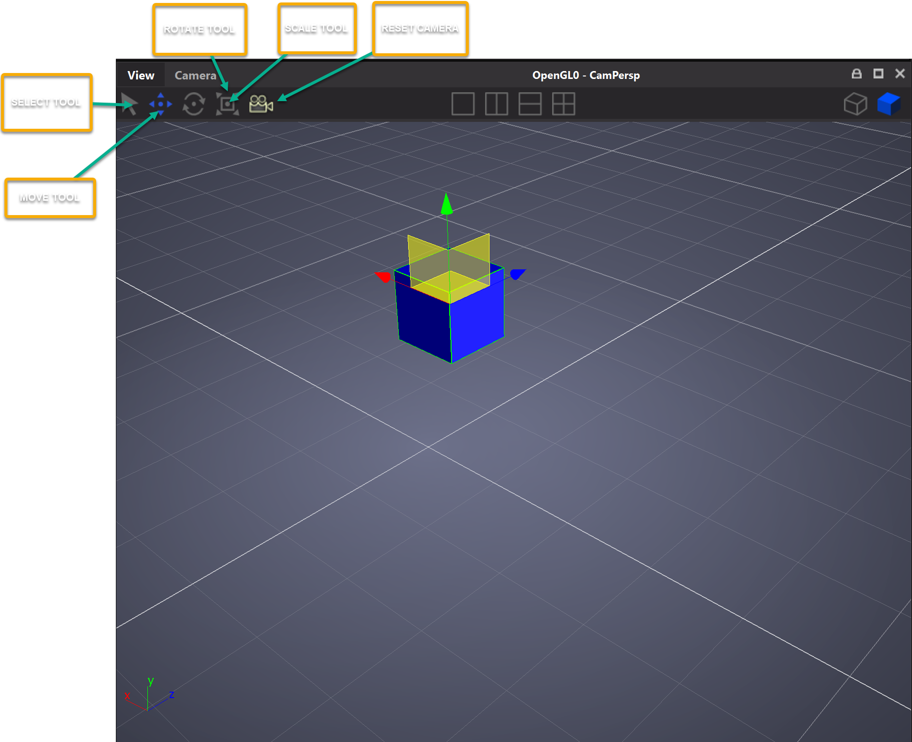
| オブジェクトの移動(Move) | w + マウスでハンドルを移動 | n/a |
次の図は移動操作を示しています。
![]()
回転
| 操作 | キーボード/マウス | タッチパッド/タッチスクリーン |
|---|---|---|
| オブジェクトの回転(Rotate) | e + マウスで回転ハンドルを操作 | n/a |
次の図は回転操作を示しています。
スケール
| 操作 | キーボード/マウス | タッチパッド/タッチスクリーン |
|---|---|---|
| オブジェクトのスケール(Scale) | r + マウスでスケールハンドルを操作 | n/a |
次の図はスケール操作を示しています。
中級 3D モデリング機能
FRI3D のユーザーインターフェースには、モデル作成を支援し高速化するための機能が複数用意されています。
スナップ
移動方向にある別のアイテムに対して、アイテムを強制的にスナップさせることができます。 スナップされるアイテムとその面は、アイテムをリリースした位置に基づいて自動的に判定されます。通常のプラントアイテムは、バウンダリ、別のプラントアイテム、またはワールドグリッドにスナップできます。ベント(vent)はバウン��ダリにのみスナップできます。
スナップ移動
スナップは別のアイテムを基準として行うことができ、移動中のオブジェクトは、移動方向にある最も近いオブジェクトの境界にスナップされます。
スナップリサイズ
別のアイテムにスナップされているアイテムを対話的にリサイズする場合、スナップ先アイテムの面を基準としてリサイズを拘束できます。 リサイズの方向がスナップ面と同一平面上にある場合、実際のリサイズは、スナップ先アイテムの当該面の寸法の範囲内に制限されます。リサイズの方向がスナップ面に直交している場合、リサイズはアイテムの反対側にのみ適用されます。この機能は、1 つ以上の方向に共通の長さを持つキャビネットなどのアイテムを整列させるのに最適です。(現時点では、リサイズ対象のアイテムが複数の面で同時にスナップ状態にある場合には正しく動作しませんが、修正中です。)
インクリメンタルな移動とリサイズ
クリック・ドラッグ・リリースによるアイテムの対話的な移動やリサイズを、ユーザーが指定した増分サイズに基づいて段階的(インクリメンタル)に行わせることができます。 これにより、アイテムの正しい位置が一定の丸め桁数で分かっている場合に、簡単に再配置できます。例えば、位置がセンチメートル単位で分かっている場合は、増分サイズを 1 cm に設定するのが適切です。
点間距離ツール
このツールを使うと、正確な点と点の間の距離を測定できます。例えば、フロアプラン上の 2 点間の距離などです。
エッジ間距離ツール
エッジ間の距離を測定する対話的なツールです。 あるアイテムのエッジにマーカーを置き、別のアイテムのエッジにもう 1 つのマーカーを置くと、2 つのマーカー間の直交距離が計算されて表示されます。 測定された距離は、関連するアイテムのいずれかが移動されるたびに動的に再計算されます。