Compartment Inspector(コンパートメントインスペクター)
FRI3D の Compartment Inspector(コンパートメントインスペクター)には、モデル内のコンパートメントが一覧表示されます。 各建屋やシステムは、複数のコンパートメントのリストに分割されます。火災モデリングでは、火災モデル全体を一連のコンパートメントに分割することで、プロセスをより細かく扱えるようになります。たとえば、オフィスビルの火災をモデル化する場合には、建物の 1 フロアを 1 つのコンパートメントと見なすことができます。 プラントであれば、スイッチギア室や中央制御室をコンパートメントと見なすことができます。1 つのコンパートメント内では複数のシナリオが発生し得ますが、これらについては後続のセクションで説明します。
コンパートメント
コンパートメントは、火災モデルに含める物理オブジェクトや火源などを内包する単位です。コンパートメント内の各サブ項目は、表現しようとするシナリオに含めることも、除外することもできます。
作成
各コンパートメントは、Boundaries(境界)、Components(コンポーネント)、Equipments(機器)、Physical Items(物理アイテム)、Simulation Items(シミュレーションアイテム)などの構成タイプから成ります。 これらの各構成エントリの意味については、以降のセクションで説明します。
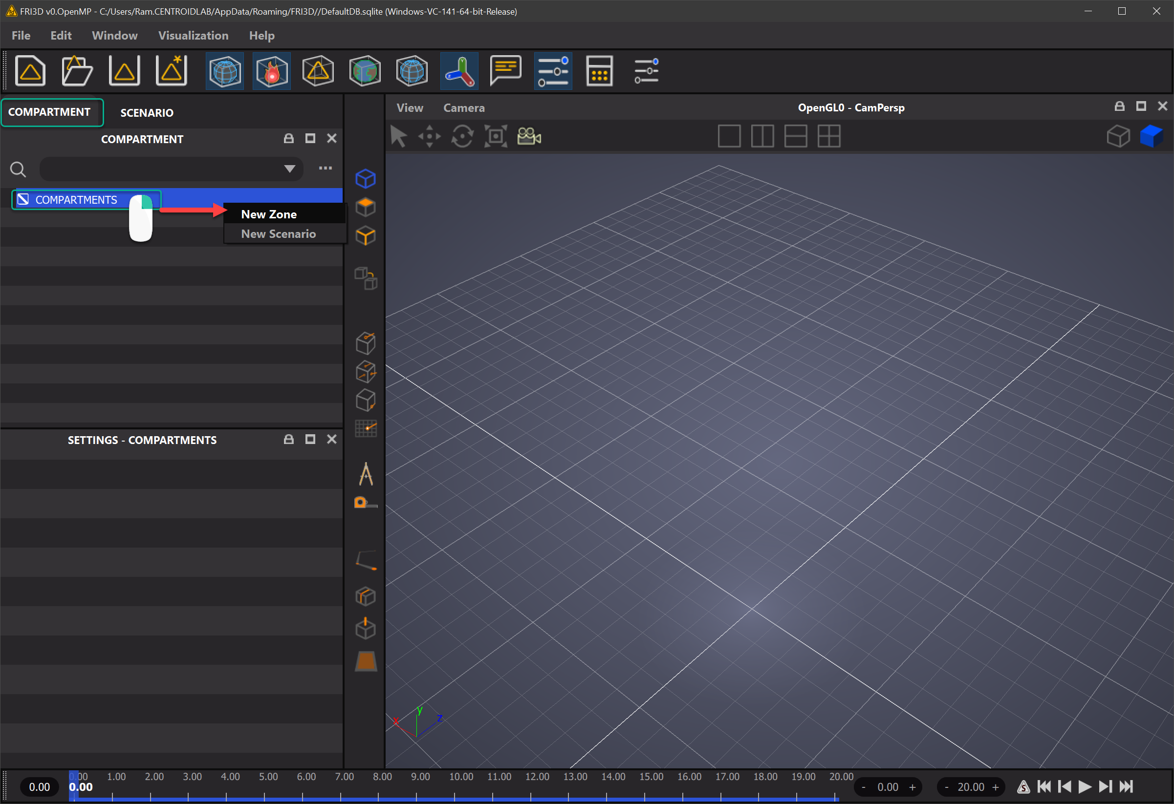
FRI3D を起動した直後の状態では、コンパートメントも境界も存在しません。次の場所を右クリックすることで新規に作成します。
COMPARTMENTS -> New Compartment
コンパートメントのエントリ
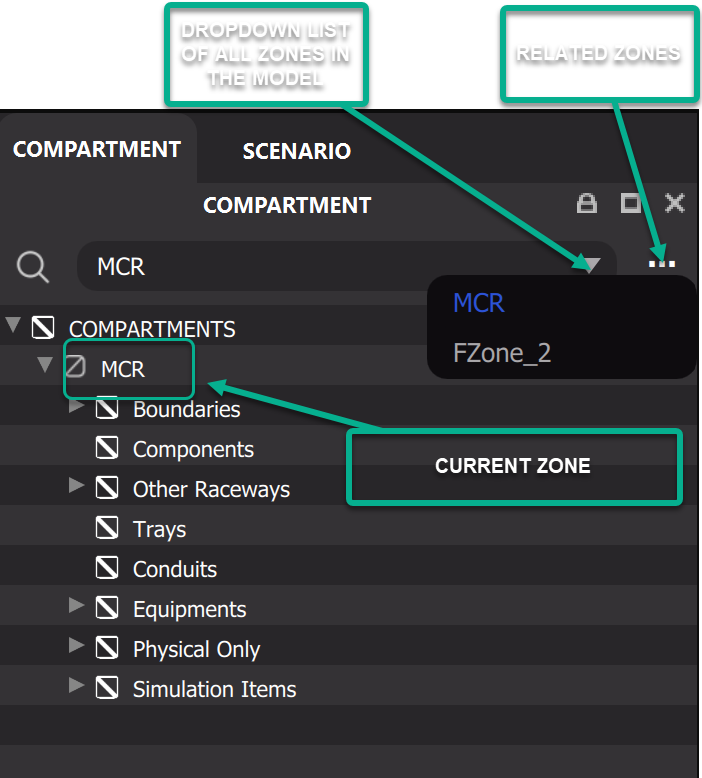
コンパートメントを作成すると、ゾーンインスペクターにいくつかのサブカテゴリが表示されます。 Compartment Inspector 上部のナビゲーションでは、次の図に示すように、その他のコンパートメントや関連するコンパートメントも表示できます。
プラントデータベース内の項目は、次の主要カテゴリのいずれかに属している必要があります。
それでは、コンパートメントの各構成要素を順に詳しく見ていきましょう。
Boundaries(境界)
コンパートメントには複数の境界エントリが含まれ、これらはすべて Boundaries の下にグループ化されます。Boundary(境界)は、壁などで仕切られた部屋や閉じた領域を表します。各境界の構築では、まず境界を作成し、それを 3D で表現する必要がある場合には、該当する境界エントリを 3D 領域にドラッグ&ドロップします。すると、その 3D 表現となるプロキシジオメトリ(立方体)が 3D モデルに読み込まれます。これで、部屋の仕様に合わせて境界を操作・調整できる状態になります。より高度な CAD モデリング手法については後の章で説明しますが、初期セットアップとしては直方体で十分です。
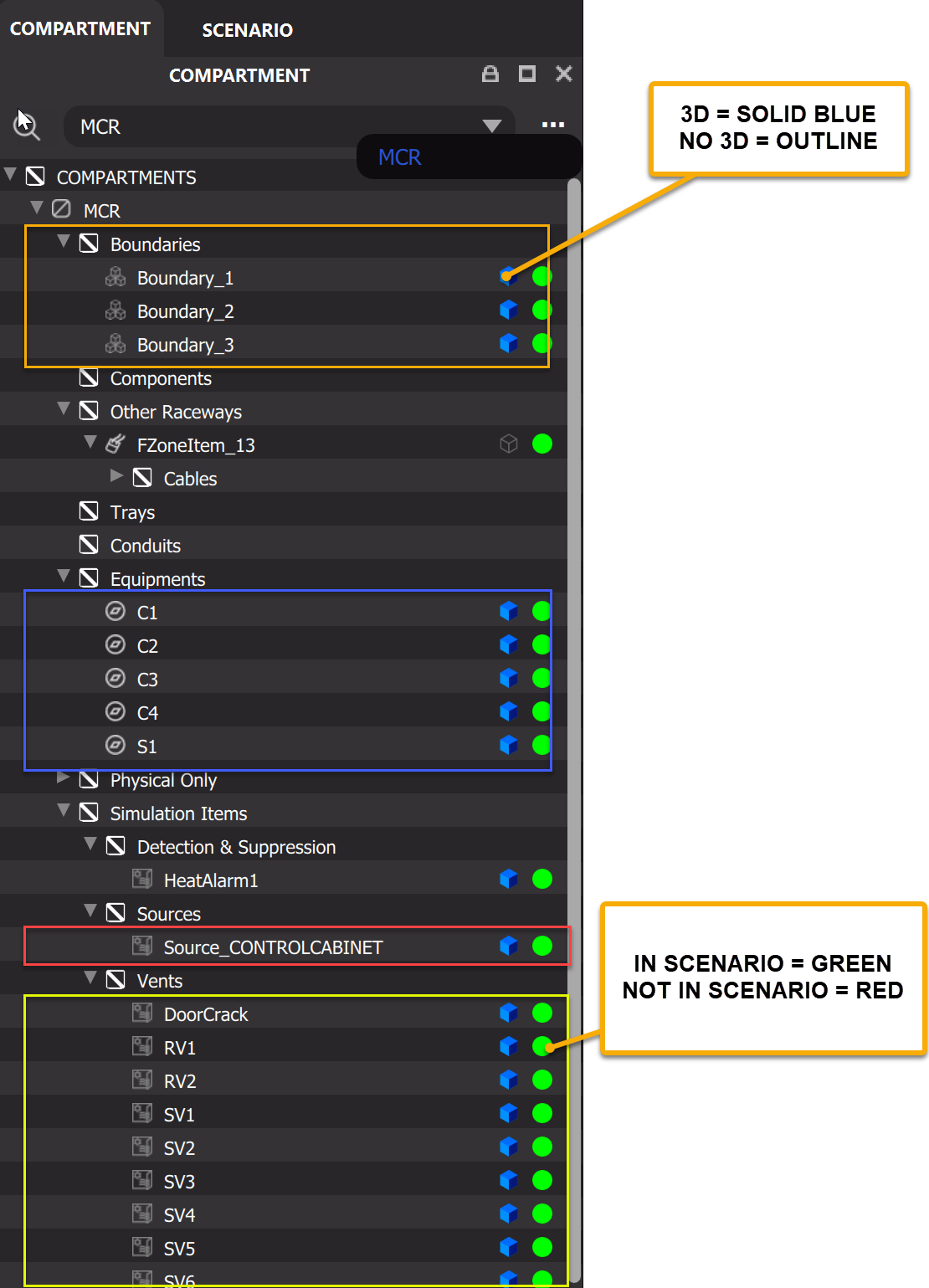
コンポーネントが追加されている場合や、既存のデータベースを開いた場合、ゾーンインスペクターには次の図のように内容が一覧表示されます。
Components と Equipments
Components -> New Component
Components(コンポーネント)は、シミュレーションに参加するコンパートメント内のオブジェクトです。コンポーネントは境界と同様の方法で、Components セクションをクリックし、右クリックから Add Component を選択するだけで作成できます。Equipments(機器)も非常によく似ており、両者の違いは意味付け上のものにすぎませんが、プラントデータベースにおいて特定の項目が Components と Equipments のどちらに置かれているかには、それなりの理由がある場合があります。
Equipments -> New Equipment
コンポーネントと機器には、故障カテゴリのほか、熱特性や材料特性を割り当てることができます。これらの割り当てについては、後のセクションで説明します。
Other Raceways と Trays
Other Raceways(その他のレースウェイ)と Trays(トレイ)は本質的に同じ項目であり、その内部にプロパティを持つケーブルを保持します。各ケーブルの材料特性は、同一の場合もあれば異なる場合もあります。
Trays -> New Tray
ケーブル
ケーブルはレースウェイの一部として作成されます。トレイまたはレースウェイに属さずに単独で存在するケーブルはありません。ケーブルは、レースウェイにケーブルを追加することで作成します。
Tray Name -> New Cable
同じケーブルが、その分岐元・分岐先に応じて複数の異なるトレイに存在する場合があることに注意してください。ケーブルには特定の材料特性が割り当てられます。その割り当てについては、後続のセクションで説明します。
Physical Only(物理のみ)
Physical Only の項目は、必ずしもシミュレーションに参加しない項目です。Physical Only の項目は Components や Equipments に変換でき、その逆の変換も可能です。
操作
コピー/貼り付け
複製
除去
削除
プロパティ
これで、シナリオを見ていく準備が整いました。
次のステップ
シナリオ